Machine Design
Gear Drive
The beam strength of gear teeth
The beam strength of gear teeth is determined from an equation (known as *Lewis equation) and the load carrying ability of the toothed gears as determined by this equation gives satisfactory results.
Lewis Equation
- Lewis assumed that as the load is being transmitted from one gear to another, it is all given and taken by one tooth, because it is not always safe to assume that the load is distributed among several teeth.
- When contact begins, the load is assumed to be at the end of the driven teeth and as contact ceases, it is at the end of the driving teeth. This may not be true when the number of teeth in a pair of mating gears is large, because the load may be distributed among several teeth.
Consider each tooth as a cantilever beam loaded by a normal load (WN) . It is resolved into two components i.e. tangential component (WT) and radial
component (WR) acting perpendicular and parallel to the centre line of the tooth respectively. The tangential component (WT) induces a bending stress which tends to break the tooth. The radial component (WR) induces a compressive stress of relatively small magnitude, therefore its effect on the tooth may be neglected. Hence, the bending stress is used as the basis for design calculations. The critical section or the section of maximum bending stress may be obtained by drawing a parabola through A and tangential to the tooth curves at B and C. This parabola outlines a beam of uniform strength, i.e. if the teeth are shaped like a parabola, it will have the same stress at all the sections. But the tooth is larger than the parabola at every section except BC.The section BC is the section of maximum stress or the critical section. The maximum value of the bending stress (or the permissible working stress), at the section BC is given by
σw = M.y / I ...(i)
where M = Maximum bending moment at the critical section BC = WT × h,
WT = Tangential load acting at the tooth,
h = Length of the tooth,
y = Half the thickness of the tooth (t) at critical section BC = t/2,
I = Moment of inertia about the centre line of the tooth = b.t3/12,
b = Width of gear face.
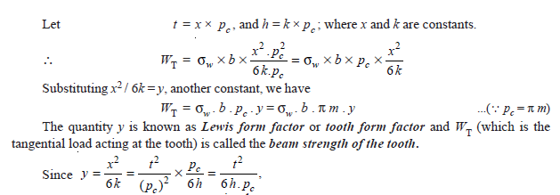
Substituting the values for M, y and I in equation (i), we get
In this expression, t and h are variables depending upon the size of the tooth (i.e. the circular pitch) and its profile.
The value of y in terms of the number of teeth may be expressed as follows :


No comments:
Post a Comment