Machine Design
Gear Drive
Wear tooth load
The maximum load that gear teeth can carry, without premature wear, depends upon the radii of curvature of the tooth profiles and on the elasticity and surface fatigue limits of the materials.
Calculations:
The maximum or the limiting load for satisfactory wear of gear teeth, is obtained by using the following Buckingham equation, i.e
Ww = DP.b.Q.K
where
Ww = Maximum or limiting load for wear in newtons,
DP = Pitch circle diameter of the pinion in mm,
b = Face width of the pinion in mm,
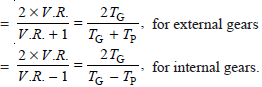
Q = Ratio factor
DP = Pitch circle diameter of the pinion in mm,
b = Face width of the pinion in mm,
Q = Ratio factor

V.R. = Velocity ratio = TG / TP,
K = Load-stress factor (also known as material combination factor) in N/mm2.
K = Load-stress factor (also known as material combination factor) in N/mm2.

where σes = Surface endurance limit in MPa or N/mm2,
φ = Pressure angle,
EP = Young's modulus for the material of the pinion in N/mm2, and
EG = Young's modulus for the material of the gear in N/mm2.
φ = Pressure angle,
EP = Young's modulus for the material of the pinion in N/mm2, and
EG = Young's modulus for the material of the gear in N/mm2.
Notes :
1. The surface endurance limit for steel may be obtained from the following equation : σes = (2.8 × B.H.N. – 70) N/mm2
2. The maximum limiting wear load (Ww) must be greater than the dynamic load (WD).
2. The maximum limiting wear load (Ww) must be greater than the dynamic load (WD).


No comments:
Post a Comment